Step-by-step guide to DC motor speed control using Arduino
You can control how fast a DC motor spins by using Arduino. This tutorial guides you through the process, even if you have never tried electronics before. You only need curiosity and a willingness to learn. You will discover how direct current motor speed control works by working with real hardware and simple code. Get ready to see your projects come to life!
Key Takeaways
Collect important parts like a DC motor, motor driver, Arduino, and potentiometer to begin your project.
Use Pulse Width Modulation (PWM) to change how fast the motor spins by changing the duty cycle.
Connect the motor driver to the Arduino the right way to keep everything safe and working well.
Write easy Arduino code to change the motor’s speed and direction so you can adjust it while it runs.
Test your setup carefully and fix common problems to make sure your project works well.
Components for DC Motor Control
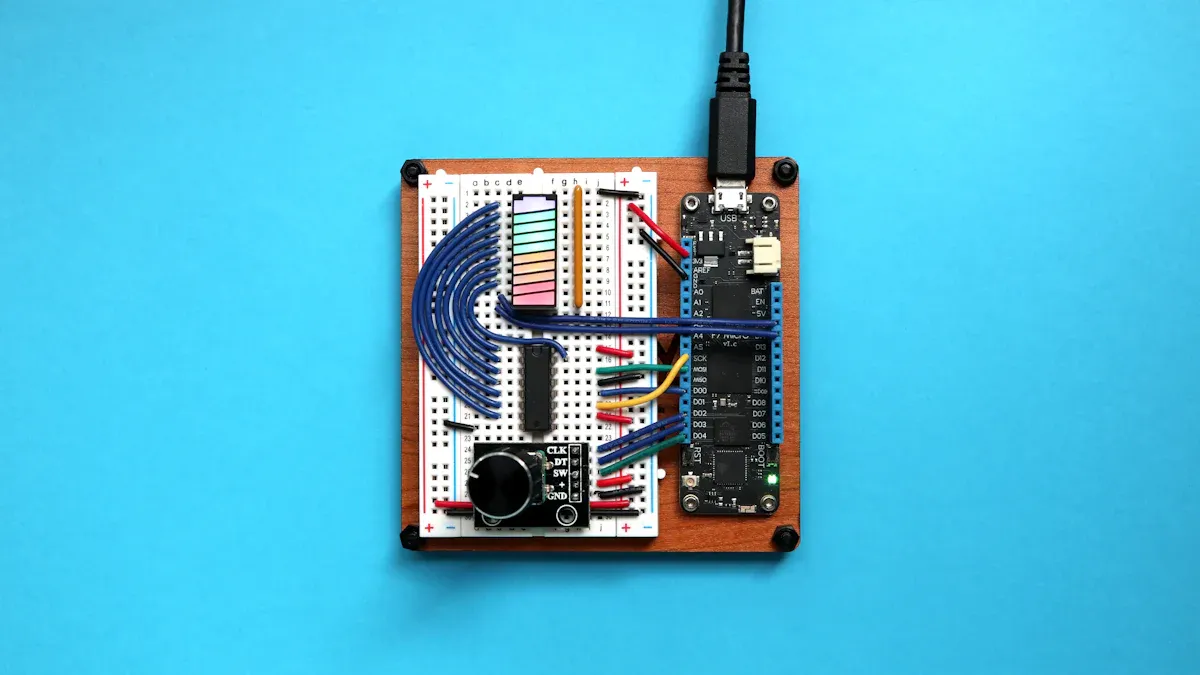
You need to collect the right parts before you begin. Every part helps with dc motor control. These parts let you connect, power, and control your motor using Arduino.
Required Parts
Here is a table that lists the usual parts found in kits for dc motor control:
Component | Description |
|---|---|
Used for basic motor control in projects. | |
l293d motor driver | Allows control of motor direction and speed. |
l298n motor driver | Dual H-Bridge driver for higher current motors. |
Arduino UNO | Main microcontroller board for your project. |
Potentiometer | Lets you adjust the speed of the motor. |
External Power Supply (6-12V) | Powers the motor and driver safely. |
Jumper Wires | Connects all the components together. |
💡 Tip: The l293d motor driver and l298n motor driver are both good options. The l293d motor driver is best for small motors. The l298n motor driver works with bigger motors. If you use arduino and l298n motor driver together, you can control two motors.
Some kits have a DC motor with a fan. This lets you see speed changes better.
Tools Checklist
You need some simple tools to build your project:
Small screwdriver
Breadboard for easy connections
Wire stripper or cutter
Multimeter to check voltage and wires
Computer with Arduino IDE installed
Some motor controllers, like the l298n motor driver, come as shields or modules. These make wiring simple and safe. The cost for a basic setup with Arduino UNO, l298n motor driver, and a DC motor is low for beginners. Advanced controllers, like the Motoron M2S24v16, cost more and have extra features.
With these parts and tools, you can start your dc motor control project. You will learn how to connect everything. You will see how the l293d motor driver and l298n motor driver help you change speed and direction.
Direct Current Motor Speed Control Basics
PWM Principle
You can change how fast a DC motor spins by using Pulse Width Modulation (PWM). PWM sends quick on and off signals to the motor. The time the signal stays on is called the duty cycle. If you make the duty cycle longer, the motor goes faster. If you make it shorter, the motor slows down. This way, you can control the power sent to the motor. It does not waste much energy as heat. PWM is very useful for direct current motor speed control. It helps you control the speed smoothly and exactly.
Most Arduino boards use a PWM frequency of about 490 Hz on most pins. Some pins can go up to 980 Hz. For example, on Arduino Uno, pins 5 and 6 use the higher frequency. This speed is good for most dc motor control projects. It works well for arduino robot car control.
Arduino Board | PWM Pins | PWM Default Frequency |
|---|---|---|
Uno, Nano, Mini | 3, 5, 6, 9, 10, 11 | 490 Hz (pins 5 and 6: 980 Hz) |
Mega | 2 - 13, 44 - 46 | 490 Hz (pins 4 and 13: 980 Hz) |
Leonardo, Micro, Yún | 3, 5, 6, 9, 10, 11, 13 | 490 Hz (pins 3 and 11: 980 Hz) |
📝 Note: You can change the PWM duty cycle to make your arduino robot car go faster or slower.
Motor Drivers Overview
To use PWM with a dc motor, you need a motor controller module. The l293d motor driver and l298n motor driver are common choices. These drivers work like switches. They let you send PWM signals from Arduino to the motor. The l293d motor driver is better at saving energy and stays cooler than the l298n. Both can do h-bridge dc motor control. This means you can change the speed and direction of the motor. The h-bridge circuit inside these modules makes it easy to control dc motors in projects like arduino robot car control.
Motor Driver | Efficiency Characteristics |
|---|---|
L298N | Uses more power, gets hotter at high currents |
L293D | Saves more power, stays cooler, less heat |
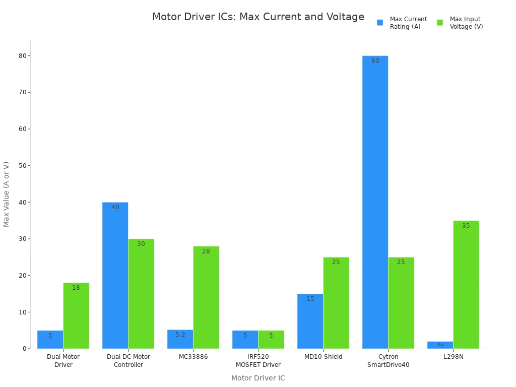
There are many kinds of motor controller modules. Some can handle bigger motors with more voltage and current. For example, the L298N can control up to four motors. It has a voltage regulator built in. This makes it good for arduino robot car control projects that need more power.
⚠️ Tip: Always think about the mechanical load when you control a dc motor. If the load changes, the motor might need more current. This can change how well PWM works and how long your motor lasts. A steady load helps your direct current motor speed control work better.
DC Motor Control Wiring
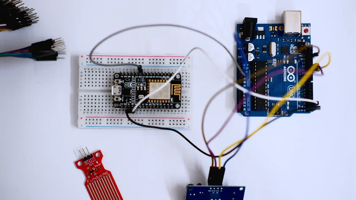
Getting your wiring right is the most important step in any dc motor control project. You need to connect the Arduino, motor driver, DC motor, and potentiometer carefully. Follow these steps to make sure your circuit works safely and reliably.
Connecting Motor Driver
Start by wiring the motor driver to your Arduino. The motor driver acts as a bridge between the Arduino and the DC motor. It lets you use small signals from the Arduino to control bigger currents for the motor.
Connect the motor driver’s input pins to the Arduino digital pins. For example:
Motor 1 Pin 2 to Arduino Pin 3
Motor 2 Pin 1 to Arduino Pin 4
Motor 2 Pin 2 to Arduino Pin 5
Use Arduino PWM pins (like Pin 9 or 10) to control the speed. Set the PWM value from 0 (off) to 255 (full speed).
Set up direction control by connecting:
Direction A to Arduino Pin 5
Direction B to Arduino Pin 4
Use Pin 6 for PWM speed control.
In your code, set the direction pins as outputs. Use
digitalWriteto set direction andanalogWriteto control speed:For forward, set DIR_A HIGH, DIR_B LOW, and PWM to 255.
For reverse, set DIR_A LOW, DIR_B HIGH, and PWM to 150.
For braking, set both direction pins LOW.
💡 Tip: Always double-check your connections before powering up. A wrong connection can damage your Arduino or motor driver.
Wiring the Motor and Power
Now, connect the DC motor and power supply. The motor driver will handle the high current needed by the motor.
Connect the DC motor terminals to the output pins of the motor driver.
Use a separate power supply for the motor. Connect the positive lead to the motor driver’s VCC and the negative lead to GND.
Connect the Arduino GND to the motor driver GND. This creates a common ground for safe operation.
Use the right wire gauge for your motor. Here is a quick guide:
Motor Type | Current Draw Consideration | |
|---|---|---|
CIM | 14 gauge | Suitable for 10-20A |
MiniCIM | 12 gauge | Higher current applications |
General | 12 gauge | For more powerful motors |
Add flyback diodes across the motor terminals if your driver does not have them built in. These diodes protect your circuit from voltage spikes when you turn off the motor.
The L293D motor driver has built-in thermal protection. It shuts down if it gets too hot, which helps prevent damage.
⚠️ Safety Note: Never connect or disconnect wires while the power is on. Always turn off your power supply before making changes.
Adding a Potentiometer
A potentiometer lets you adjust the speed of your DC motor by turning a knob. You can use it to control speed with a potentiometer in real time.
Connect one outer pin of the potentiometer to 5V on the Arduino.
Connect the other outer pin to GND.
Connect the middle pin (wiper) to an analog input pin on the Arduino, such as A0.
In your code, read the analog value from the potentiometer. Map this value to a PWM range (0-255) and send it to the motor driver’s PWM pin.
A potentiometer does not directly control motor speed. It adjusts the power sent to the motor, which changes the speed for a given load. If the load changes, the speed may vary. This method works well for most beginner projects.
You can also use a potentiometer with an L298N driver to control both speed and direction. This setup gives you more flexibility for h-bridge dc motor control.
📝 Note: Using a potentiometer makes your dc motor control project interactive and fun. You can see instant changes in speed as you turn the knob.
PWM DC Motor Control Code
Writing the Code
You can bring your DC motor project to life by writing a simple program. This code lets you use PWM speed control to adjust how fast your motor spins. You will use the Arduino IDE to write and upload the code.
Here is a sample Arduino example code for controlling two DC motors with PWM. This code works well with the arduino and l298n motor driver setup.
// Left motor pins
#define ENA 9     // ENA speed pin for left motor
#define IN1 8     // IN1 on Motor controller board
#define IN2 11    // IN2

// Right motor pins
#define ENB 10    // ENB speed pin for right motor
#define IN3 12    // IN3 on Motor controller board
#define IN4 13    // IN4

int rightspeed = 150;
int leftspeed = 150;

void setup() {
    pinMode(ENA, OUTPUT);
    pinMode(IN1, OUTPUT);
    pinMode(IN2, OUTPUT);
    pinMode(ENB, OUTPUT);
    pinMode(IN3, OUTPUT);
    pinMode(IN4, OUTPUT);
    analogWrite(ENA, leftspeed);
    analogWrite(ENB, rightspeed);
}

void loop() {
    digitalWrite(IN1, HIGH);
    digitalWrite(IN2, LOW);
    digitalWrite(IN3, HIGH);
    digitalWrite(IN4, LOW);
}
This code sets up the pins for both motors. You use the analogWrite() function to send a PWM signal to the ENA and ENB pins. The value you set (from 0 to 255) changes the duty cycle. A higher value means the motor spins faster. You can change the rightspeed and leftspeed variables to test different speeds.
You can also add a potentiometer to control the speed in real time. Read the analog value from the potentiometer and map it to the PWM range. This lets you turn the knob and see the motor speed change instantly.
Uploading and Running
You can upload your code to the Arduino board using the Arduino IDE. Follow these steps for a smooth process:
Connect your Arduino to your computer with a USB cable.
Open the Arduino IDE and paste your code into a new sketch.
Select the correct board and port from the Tools menu.
Click the Upload button (the right arrow icon).
Once the upload finishes, your Arduino will start running the code. The motors will spin at the speed you set in the code. If you use a potentiometer, you can adjust the speed while the program runs.
The PWM dc motor control works by sending fast on and off signals to the motor driver. The ENA and ENB pins on the driver receive these signals. The average voltage sent to the motor depends on the duty cycle of the PWM signal. When you increase the duty cycle, the motor gets more power and spins faster. When you lower the duty cycle, the motor slows down.
PWM adjusts the amplitude of the input voltage to the motor.
The average voltage applied to the motor is proportional to the duty cycle of the PWM signal.
A higher duty cycle leads to a higher average voltage and thus a higher motor speed.
The ENA and ENB pins of the motor driver control motor speed.
Sending a PWM signal to these pins allows for speed regulation by adjusting the duty cycle.
A higher duty cycle results in faster motor speeds, while a lower duty cycle results in slower speeds.
You can use this method for many projects that need pwm speed control. Try changing the speed values or using a potentiometer to see how the motor responds. This hands-on approach helps you understand how pwm dc motor control works in real time.
🛠️ Tip: If your motor does not spin, check your wiring and make sure the power supply is connected. Double-check the pin numbers in your code to match your hardware setup.
Testing and Troubleshooting
Testing Steps
You need to test your DC motor speed control project to make sure everything works as expected. Follow these steps to check your setup:
Gather all necessary components, such as your Arduino board, DC motor, and any display like an LCD if you want to show speed.
Double-check your wiring. Make sure each connection matches your circuit diagram.
Set up your Arduino code with the correct pin modes for motor control and speed measurement.
Upload your code to the Arduino. Watch for any error messages in the Arduino IDE.
Power on your circuit. Observe the motor as you adjust the potentiometer or change the PWM value in your code.
If you use a display, check that it shows the PWM duty cycle and motor speed in RPS (revolutions per second) or RPM (revolutions per minute).
Use a multimeter to measure voltage across the motor terminals. The voltage should change as you adjust the speed.
🛠️ Tip: Always start with a low power setting. Increase the speed slowly to avoid damaging your motor or driver.
Common Issues
You might face some problems during testing. Here are common issues and how you can troubleshoot them:
The motor turns on for a second and then off repeatedly. This could mean erratic behavior or a wiring problem.
Voltmeter readings jump between 0V and 2V. This suggests an unstable voltage supply.
The potentiometer does not change the motor speed. The voltage across the motor stays the same, even when you turn the knob.
The PWM signal may not reach the motor driver. Use a multimeter or oscilloscope to check the signal from the Arduino pin.
If the L298N shield stops working when the voltage drops below 5V, check your power supply. The shield needs enough voltage to work.
Make sure you set the PWM pin as an output in your code. If not, the motor will not respond.
All grounds must connect together. If you miss a ground connection, the circuit may not work.
Some motors need a PWM value above a certain level (like 80) to start spinning.
Check that the H-bridge driver inputs are set correctly. Wrong settings can stop the motor.
If you use an ESC, make sure you send the correct PWM duty cycle and connect SPEED GND to Supply GND as needed.
⚡ Note: Careful troubleshooting helps you learn more about electronics and makes your project more reliable.
You now know how to control a direct current motor’s speed using Arduino. Try out different motor drivers to make your project better. Here are some well-known choices:
Motor Driver | Key Features |
|---|---|
L293D | Easy to use, works well, not expensive, good for beginners |
L298N | Can handle more current, good for bigger motors |
DRV8833 | Uses less power, uses MOSFETs, does not get hot easily |
TB6612FNG | More efficient, works with lower voltage, small size |
You can change speed and direction by adding an H-bridge or using the L293D chip. For more practice, look at these resources:
Guides that show how to change motor direction with Arduino and H-bridge circuits
Experiments using L293D to spin motors left or right, and to speed up or slow down
If you want to learn more, try advanced direct current motor speed control methods like closed-loop control and nested torque-speed loops. These methods help you control both torque and speed for better results.
FAQ
How do you choose the right motor driver for your project?
You should check your motor’s voltage and current. Pick a driver that matches or exceeds these values. For small motors, use L293D. For bigger motors, use L298N. Always read the datasheet before you start.
Why does your motor not spin when you upload the code?
Check your wiring first. Make sure all grounds connect together. Confirm the power supply works. Double-check the pin numbers in your code. If you use a potentiometer, test it with a multimeter.
Can you control both speed and direction with Arduino?
Yes, you can. Use PWM to set the speed. Use two digital pins to set the direction. Change the HIGH and LOW values in your code to reverse the motor.
What is the safest way to power your DC motor?
Use a separate power supply for the motor. Connect the grounds together. This keeps your Arduino safe from high currents. Never power a large motor directly from the Arduino board.
How do you use a potentiometer to control motor speed?
Connect one side of the potentiometer to 5V, the other to GND, and the middle pin to an analog input. In your code, read the analog value and map it to a PWM output.
See Also
Master Arduino Vibration Motors in Just Five Simple Steps
Adjusting Vibration Motor Strength Using Arduino PWM Techniques
Utilizing 3V DC Motors Across Five Different Devices
Ten Effective Vibration Motors to Enhance Your Arduino Projects
Get Custom Micro DC Motors from
INEED Motors!
Leading Brand in Vibration Motor Manufacturing Industry
