How to Read and Understand Motor Diagrams

Motor diagrams are crucial for those who want to read and understand motor diagrams related to electrical systems. They assist in quickly identifying problems and creating more efficient setups. For instance, utilizing numbers such as +1, 0, or -1 for motor components aids in pinpointing issues and reducing noise. This simplifies the process of diagnosing power system problems. Gaining knowledge of motor diagrams enables you to detect faults and enhance systems. Regardless of your experience level, mastering these diagrams saves time and enhances troubleshooting skills.
Key Takeaways
Motor diagrams make electrical systems easier to understand and fix fast.
Knowing symbols and notes in motor diagrams helps you read them correctly.
Datasheets give details about motor parts, helping you pick the right ones.
Avoid errors like reading symbols wrong or skipping missing data to get better.
Practice with real examples and INEED's tools to learn and feel more confident.
Basics of Motor Diagrams
What Are Motor Diagrams
Motor diagrams are pictures that show how electrical parts connect. They include motors, switches, and relays. These diagrams make hard systems easier to understand. They show how electricity moves in a circuit. You can use them to design, fix, or take care of motor systems. By looking at these diagrams, you can find problems like bad connections or circuits carrying too much power before they get worse.
Motor diagrams have changed with new technology. Old systems used mechanical parts. Now, many diagrams use programmable logic controllers (PLCs). This shows why learning motor diagrams is important to keep up with changes. For example, knowing the difference between NEMA and IEC standards helps you make circuits that follow rules. Motor diagrams also remind us to use overload protection. This keeps systems safe and working well.
Types of Motor Diagrams
Motor diagrams come in different kinds, each for a special job. The table below shows some motor types and what they do:
Type of Motor | Characteristics and Uses |
|---|---|
Induction Motors | Strong and good for general jobs needing steady work. |
Reversible Motors | Can switch directions quickly, great for start/stop tasks like moving conveyors. |
Electromagnetic Brake Motors | Have brakes that work when power is off, used for lifting or vertical tasks. |
Torque Motors | Give strong starting power, work well when stopped, good for winding or tension jobs. |
Synchronous Motors | Spin at the same speed as the power frequency, used in things like clocks. |
DC Motors | Smaller than AC motors, save energy, and run on direct current. |
Knowing these types helps you pick the right motor. For example, if you need strong starting power, a torque motor is a good choice.
Why Motor Diagrams Are Important in Industries
Motor diagrams are very useful in industries. They give details to help install, run, and fix motor systems. The table below explains their importance:
Aspect | Description |
|---|---|
Installation | Show sizes and spots needed to set up motors correctly. |
Specifications | Explain motor details not listed on the nameplate. |
Operational Reliability | Help keep motors running well by showing where to lubricate and maintain. |
Clearances | Show space needed for air flow and placing equipment. |
Using motor diagrams helps you design safe and efficient circuits. They also help you take care of equipment by showing key areas like lubrication points.
Key Components in Motor Diagrams
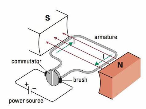
Power Sources and Their Role
Power sources are the main energy providers for motor systems. They give the power needed to run motors and other parts. Knowing their role helps you check motor performance.
Motors use power to turn electricity into motion. This is how they do their job.
Input and output power stay balanced, even with gear changes. This shows why power sources are key for steady motor work.
Motor curves show things like speed, torque, and efficiency. These help you see how power sources affect the system.
When reading motor diagrams, look at how power sources connect. This ensures the motor gets the right voltage and current to work well.
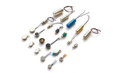
Motors, Including INEED's Vibration Motor
Motors are the most important part of motor diagrams. They change electrical energy into movement, making the system work. INEED's vibration motors are special because they are efficient and flexible.
Parameter | Description |
|---|---|
Peak | Shows the strongest vibration over a set time. |
RMS | Tells the average vibration strength, showing the load. |
Crest Factor | Compares the strongest vibration to the average, showing changes. |
INEED's motors work well with 2 to 5 volts and need 50 to 100 milliamps. They are built to last, with tests like start-stop cycles checking their durability.
Different motors have different benefits. Iron shell motors vibrate more strongly, while plastic ones are quieter. The table below compares them:
Motor Type | Vibration Strength (m/s²) | Noise Reduction (dB(A)) |
|---|---|---|
Iron Shell Motor | 0.36 | -5 |
Plastic Motor | 0.22 | -4 |
INEED's motors are great for jobs needing steady and exact performance. Their small size and custom options make them useful in many circuits.
Switches, Relays, and Protective Devices
Switches, relays, and safety devices are key in motor diagrams. They keep the circuit safe and working properly by controlling and protecting parts.
Switches let you turn electricity on or off manually or automatically. They control when the motor runs. Relays use magnets to manage circuit connections. This keeps control parts safe from power spikes.
Safety devices, like thermal relays and breakers, protect motors from damage. Each has a job:
Thermal relays stop motors from overheating by cutting power when it's too hot.
Circuit breakers guard against electrical problems, keeping motors within safe limits.
Adding these parts to your motor diagram makes the circuit safe and efficient. Knowing how they work helps you fix problems and keep the system running well.
Sensors and Controllers in Motor Systems
Sensors and controllers are key parts of motor systems. They work together to help motors run well and meet performance goals. Sensors collect live data, while controllers use this data to make changes for better motor function.
Role of Sensors in Motor Systems
Sensors give important feedback to check and control motor work. They measure things like position, speed, and torque to keep the motor working right. Without sensors, controlling motors accurately would be very hard.
Hall Effect Sensors: These find the rotor's position in a motor. They are helpful in cars, like in electric power steering (EPS). By giving exact rotor position data, they improve motor life and efficiency.
Feedback Sensors: These watch motion and send data to the controller. They compare actual motion with the planned path to keep the motor on track.
For example, feedback sensors in a motor system spot problems. They let the controller fix them quickly to keep the motor running smoothly.
Role of Controllers in Motor Systems
Controllers are like the motor system's brain. They take sensor data and decide how to adjust the motor. This keeps the motor safe and working well.
Controllers check sensor data against performance goals.
They tell the motor to change speed, torque, or position as needed.
This keeps the motor steady and working as planned.
Modern controllers use smart algorithms to improve motor work. For example, in INEED's vibration motors, controllers can change vibration strength and speed for specific tasks.
How Sensors and Controllers Work Together
Sensors and controllers team up to make motor systems reliable. Here's how they work:
Sensors gather live data like speed, position, and torque.
They send this data to the controller, which checks it against set goals.
The controller adjusts the motor to keep it working correctly.
Tip: Think of sensors as the motor system's eyes and ears, and controllers as its brain. Together, they form a loop that keeps the motor running well.
By learning about sensors and controllers, you can read motor diagrams better and fix problems easily. Whether you're using simple motors or advanced ones like INEED's vibration motors, knowing these parts helps you design and maintain great motor systems.
How to Read and Understand Motor Diagrams
Decoding Symbols and Notations
Motor diagrams use symbols to show parts and their jobs. Knowing these symbols is key to understanding motor diagrams. Each symbol gives important details about the system, helping you find parts and their purposes.
Here are some common symbols and what they mean:
Reference Designators: Labels like R1 for resistors or C5 for capacitors mark parts in the diagram.
Common Symbols:
R: Resistor
C: Capacitor
L: Inductor
D: Diode
Q: Transistor
U: Integrated Circuit
To understand motor diagrams better, learn specific notations too. The table below explains key parts and their meanings:
Component | Description |
|---|---|
Ex Symbol | Shows motors made for risky, explosive areas. |
Power | Measured in kilowatts (kW) or horsepower (hp). |
Voltages | Delta (△) for low-voltage, star (Y) for high-voltage setups. |
Speed/RPM | Top speed in revolutions per minute without load. |
Efficiency | Shown by an IE number, crucial for motor work. |
IP Rating | Tells protection level from dust and water. |
Other Information | Includes bearing sizes, heat limits, insulation type, and duty cycle. |
Tip: Learn these symbols and notations to read motor diagrams well. This will help you fix and design motor systems confidently.
Tracing Connections and Voltage Nodes
Tracing connections and voltage nodes ensures the circuit works right. By following electricity flow, you can spot problems and check if parts are connected properly.
To trace connections well, follow these tips:
Explanation | |
|---|---|
Use clear and unique labels | Makes circuits easier to understand and reduces mistakes. |
Add custom node names | Helps make reports and graphs more detailed and user-friendly. |
Show input/output gate types | Improves circuit visuals without changing the NETLIST. |
Start by finding the power source and follow the electricity path. Look for voltage nodes, which show where electrical potential is measured. These nodes explain how voltage spreads in the system.
Note: Always check connections and voltage nodes twice. This ensures the circuit is safe and works well. Wrong connections can cause failures or damage.
Using Datasheets for Component Details
Datasheets give detailed info about motor system parts. They help you understand each part's specs and abilities, so you can make smart choices when fixing or designing motor diagrams.
When reading datasheets, focus on these points:
Electrical Specifications: Check voltage, current, and power ratings to match your motor system.
Mechanical Properties: Look at size, mounting options, and weight to ensure the part fits.
Performance Metrics: Review efficiency, speed, and torque to see if the part works for your needs.
For example, INEED's vibration motors have datasheets with details like peak vibration, RMS values, and crest factors. These help you know how the motor performs in different situations.
Tip: Keep datasheets nearby when working on motor diagrams. They are useful for checking part details and improving system performance.
By using these methods, you can better understand motor diagrams. This will improve your skills in fixing, designing, and maintaining motor systems.
Avoiding Common Mistakes in Diagram Interpretation
Reading motor diagrams can be hard if you're not careful. Knowing common mistakes helps you avoid errors that cause bad designs or delays. Below are some frequent problems and how to prevent them.
Misreading Symbols and Notations
A big mistake is mixing up symbols. Each symbol in a motor diagram has a clear meaning. Confusing them can mess up the whole system. For example, thinking a resistor is a capacitor could lead to wrong wiring.
Tip: Keep a chart of motor symbols close by. This helps you check any symbols you don't know.
Ignoring Missing or Incomplete Data
Missing data in diagrams can cause big issues. If voltage ratings or torque details are missing, you might pick the wrong motor or create unsafe setups. Old or wrong data can also lead to bad results.
Duplicate or odd data can give false results.
Always check diagrams for missing details. If something is unclear, use datasheets or manuals to fill in the gaps.
Misinterpreting Graphs and Visuals
Graphs and visuals in diagrams are helpful but can be tricky. If you read them wrong, you might make bad decisions. For example, a graph with a cut-off Y-axis might make small differences look big.
Start graph axes at zero unless there's a good reason not to.
Use simple colors to avoid confusion.
Add clear titles and labels for better understanding.
Note: Misleading visuals waste time and resources. Keep designs simple for clear reading.
Overlooking Voltage Nodes and Connections
Not checking connections and voltage nodes can cause circuit problems. Skipping this step might hide loose wires or wrong setups. These can lead to short circuits or poor motor performance.
Label all connections clearly to avoid mistakes.
Use custom names for nodes to make diagrams easier to follow.
Check input and output gates for proper matching.
Carefully tracing connections ensures the circuit works as it should.
Misunderstanding Correlation and Causation
Another mistake is thinking correlation means causation. For example, if a motor overheats at high speed, you might think speed is the only reason. But other things, like bad cooling or heavy loads, could also be to blame.
Tip: Look at all possible causes before making changes. Fix the real problem, not just the symptoms.
Neglecting Accessibility in Diagram Design
Cluttered diagrams confuse even experts. Too many colors or missing labels make them hard to read. This is worse for people with color blindness.
Use patterns or labels along with colors for clarity.
Keep designs simple and easy to understand.
Avoid adding too much detail to the diagram.
Simple designs make diagrams easier for everyone to read.
Skipping Regular Reviews and Updates
Diagrams should show the system's current state. Old diagrams can cause mistakes during repairs or upgrades. Regular updates keep diagrams accurate and useful.
Reminder: Treat diagrams like living documents. Update them whenever the system changes.
By avoiding these mistakes, you can read motor diagrams better. This saves time and makes motor systems safer and more efficient.
Practical Tips for Beginners
Begin with Easy Motor Diagrams
Start with easy motor diagrams to learn the basics. These diagrams show simple parts like motors, switches, and power sources. They help you see how electricity moves without being confusing.
A brushless motor is a simple system to study. Its design is easy to understand, making it perfect for beginners.
Choose diagrams with clear labels and few parts. This helps you focus on learning the basics before tackling harder systems.
Starting simple builds your confidence. It ensures you learn important details step by step.
Understand Common Symbols and Their Uses
Motor diagrams use symbols to show parts. Learning these symbols is like learning a new language. It helps you know what each part does in the system.
Learn the names of circuit parts. For example, "R" means resistor, and "C" means capacitor.
Know that symbols can differ by country. Understanding this helps you read diagrams from different places.
Match symbols to real-life parts. This makes reading diagrams faster and easier.
Tip: Keep a chart of symbols nearby. It’s helpful when you’re just starting.
Try Real-Life Examples
Practicing with real examples is the best way to learn. It helps you use what you’ve learned and gain hands-on experience.
Build simple circuits using a breadboard and basic parts. Follow steps to put them together and test them.
Move to microcontrollers when you’re ready. They show how motors react to electrical signals.
Experiment with INEED’s vibration motors. Their small size and flexible features are great for beginners.
Real-life practice connects learning to doing. It also improves your problem-solving skills, which are key for motor systems.
Learn About INEED's Tools for Vibration Motor Use
INEED provides many tools to help you use vibration motors. These tools show how to pick, use, and improve motors for your needs. Whether you're new or experienced, INEED's guides can help you learn and get better results.
Why Use INEED's Tools?
INEED's tools mix expert knowledge with real-world uses. You can find guides, datasheets, and notes explaining how to use vibration motors in different fields. These resources make hard ideas simple, helping you add motors to your projects easily.
Tip: Check INEED's application page to see how vibration motors work in wearables, healthcare, and more. This shows how flexible they are.
How INEED's Solutions Help in Real Life
People have shared how INEED's vibration motors helped them. Here are some stories:
One person healed faster and had better blood flow after a foot injury.
Another felt more active and healthier after daily use.
A woman over 65 got rid of pain and started exercising more.
Someone improved their balance and reduced pain in just a week.
A study showed vibration therapy helps athletes and people with bone issues.
These stories show how INEED's vibration motors can help in real life. By using their tools, you can make the most of vibration motor technology for your projects.
Reminder: Visit INEED's website to find these tools and learn how to use vibration motors in your designs.
Advanced Applications of Motor Diagrams
Customizing Motor Systems with INEED's Vibration Motor
Making motor systems fit your needs is simpler with INEED's vibration motors. These motors are very efficient, last a long time, and offer precise control. They are perfect for advanced uses. Adding these motors to your system improves performance and meets specific needs.
Metric | INEED's Vibration Motor | Traditional Motors |
|---|---|---|
Efficiency | Average | |
Durability | Long-lasting | Wears out faster |
Precision Control | Excellent | Limited |
Motor diagrams help you customize systems. They show how to start motors, check performance, and see results. For example, you can graph speed, torque, and voltage changes over time. Automated testing lets you try different setups to find the best one.
Feature | Description |
|---|---|
Use starters like VFDs to lower power surges. | |
Graphical Simulation | See how speed, torque, and voltage change visually. |
Result Analyzer | Compare setups to find the worst-case scenario. |
Tip: Use motor diagrams to make your system efficient and reliable.
Integrating Motor Diagrams in IoT and Smart Devices
Motor diagrams are key for adding motors to IoT and smart devices. They help you design circuits that connect sensors, controllers, and motors smoothly. This ensures all parts work together without issues.
For instance, in a smart home, motor diagrams show how to link vibration motors to controllers. This creates touch feedback for alerts or notifications. By following connections and voltage points, you can make sure the circuit works well.
IoT devices need small, energy-saving motors. INEED's vibration motors are great for this. They are tiny and use little power, making them easy to add to smart devices. This improves user experience without using too much battery.
Note: Always update motor diagrams when your IoT system changes. This keeps your circuit correct and dependable.
Enhancing User Experience with Haptic Feedback Solutions
Haptic feedback makes devices more interactive by adding touch sensations. Motor diagrams help you design circuits that create accurate vibrations, improving the user experience. INEED's vibration motors are great for this because they are customizable and perform well.
Sector | Application | Benefits |
|---|---|---|
Consumer Electronics | Phones and wearables | Better interaction and satisfaction. |
Healthcare | Surgery training and recovery | Realistic touch for improved results. |
Gaming | Virtual reality and controllers | More realistic and engaging experiences. |
Automotive | Smart and self-driving cars | Quiet alerts and better driver focus. |
Haptic feedback also helps people with disabilities use devices. It lets them interact through touch, making technology more inclusive. This shows why designing circuits for all users is important.
As people want more immersive experiences, haptic technology is growing. Using motor diagrams helps you add vibration motors to your devices. This makes your products stand out in the market.
Learning motor diagrams helps you fix and create systems better. These diagrams break down tricky circuits, making problems easier to spot and fix. Practicing often improves your skills and boosts your confidence. Check out INEED's website for helpful guides, datasheets, and tools to aid your learning.
Tip: INEED's vibration motors are precise and work efficiently for advanced uses. Their adjustable features make them perfect for fields like healthcare, wearables, and IoT. Visit INEED Motors to see how these motors can improve your projects.
FAQ
What is the purpose of motor diagrams?
Motor diagrams show how electrical parts connect and work together. They make hard systems easier to understand. This helps you fix, design, and take care of motor systems. By studying them, you can find problems like bad connections or circuits carrying too much power before they get worse.
How do you identify symbols in motor diagrams?
Symbols in motor diagrams stand for parts like resistors, capacitors, and motors. A chart can help you match symbols to their meanings. For example, "R" means resistor, and "C" means capacitor. Learning these symbols makes reading diagrams easier.
Tip: Keep a chart of symbols nearby for quick help.
Why are INEED's vibration motors ideal for beginners?
INEED's vibration motors are small, energy-saving, and simple to use. Their adjustable features make them great for learning and trying out motor systems. You can use them in many ways, like in wearables or health devices, while gaining real-world experience.
Can motor diagrams help in IoT projects?
Yes! Motor diagrams show how to connect motors, sensors, and controllers in IoT devices. They help everything work smoothly. For example, INEED's vibration motors can add touch feedback to smart devices, making them more interactive and useful.
Where can you find resources to learn motor diagrams?
Check INEED's website for guides, datasheets, and examples. These resources explain motor systems clearly and give real-life examples. They also show how to use INEED's vibration motors in different fields, helping you learn and improve.
Reminder: Visit INEED Motors for helpful tools and expert advice.
See Also
Exploring Motor Diagrams: Types, Components, and Their Uses
Identifying and Fixing Frequent Problems with 3 Volt Motors
How to Manage the Rotation Direction of Motors
Selecting Ideal Configurations for Battery Operated Electric Motors
Get Custom Micro DC Motors from
INEED Motors!
Leading Brand in Vibration Motor Manufacturing Industry